This wind tunnel model is a bit unusual because only one part of the aircraft is shown and the part of the fuselage in question has been rendered as a longitudinal section in order to be set on a stand (an aluminium plate).
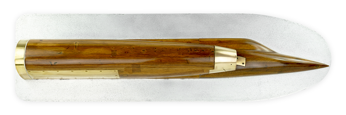
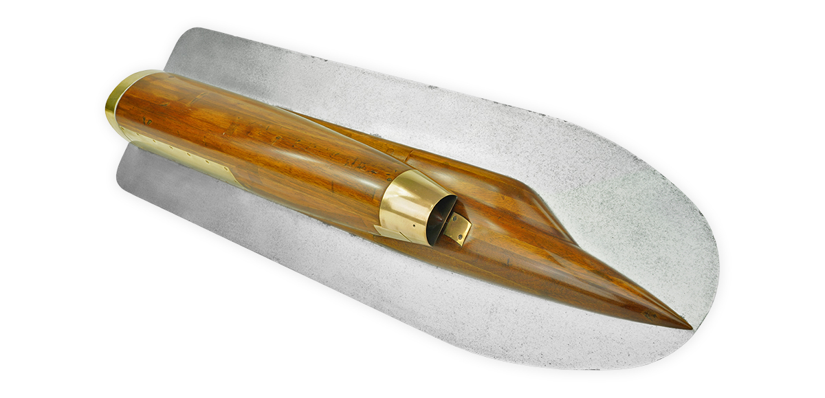

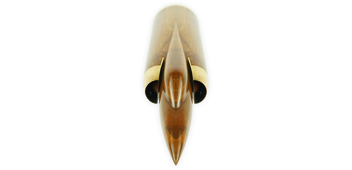
The outline of the airplane made of wood and brass is true to the Mirage III, so is the shape of the distinctive air intake. Therefore, this is undoubtedly a tool used in the development process of this legendary aircraft as demonstrated by the photo montage below.
The purpose of this technical piece was to perform measures at the level of the external part of the air intake but primarily on the inside and all along the airflow of the jet engine. This is more obvious on the rear side of the plate. This is where hookups were made to a set of small pipes all connected to just as many small holes located inside the airflow. Once connected to the measuring instruments, they captured the pressure that enabled the display and the recording of the test results.

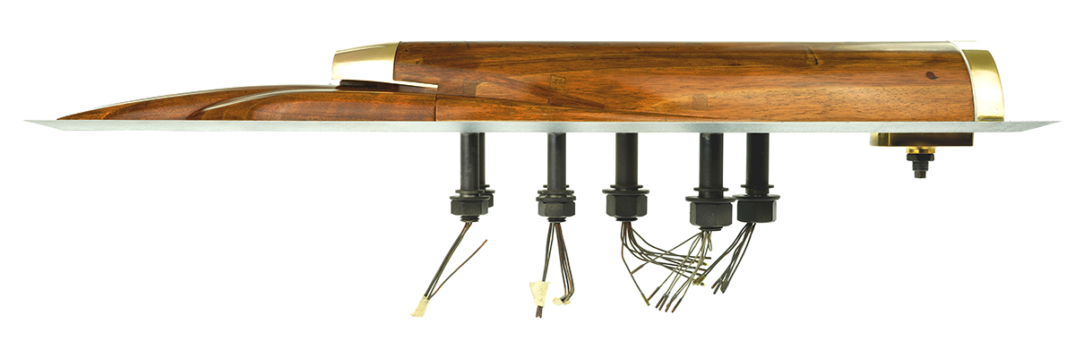
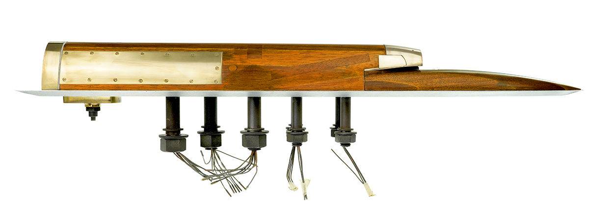
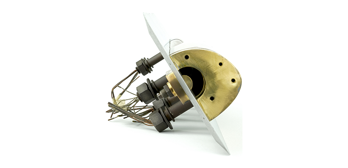

Taking measurements inside the airflow is clearly the purpose of this object. However, it is difficult to determine the purpose of the tests that were performed. Was it to test different shapes of air intakes, the boundary layer trap system, the shape of the shock cone or the incidence of its various positions (we can see on the model that the shock cone is located way back the air entry) …?
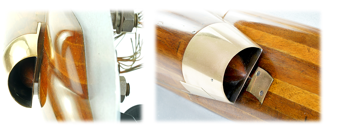
It should be noted that this piece is very difficult to photograph and that the shots do not do it justice. In reality it is much nicer and with better proportions than it appears to be on the photos.
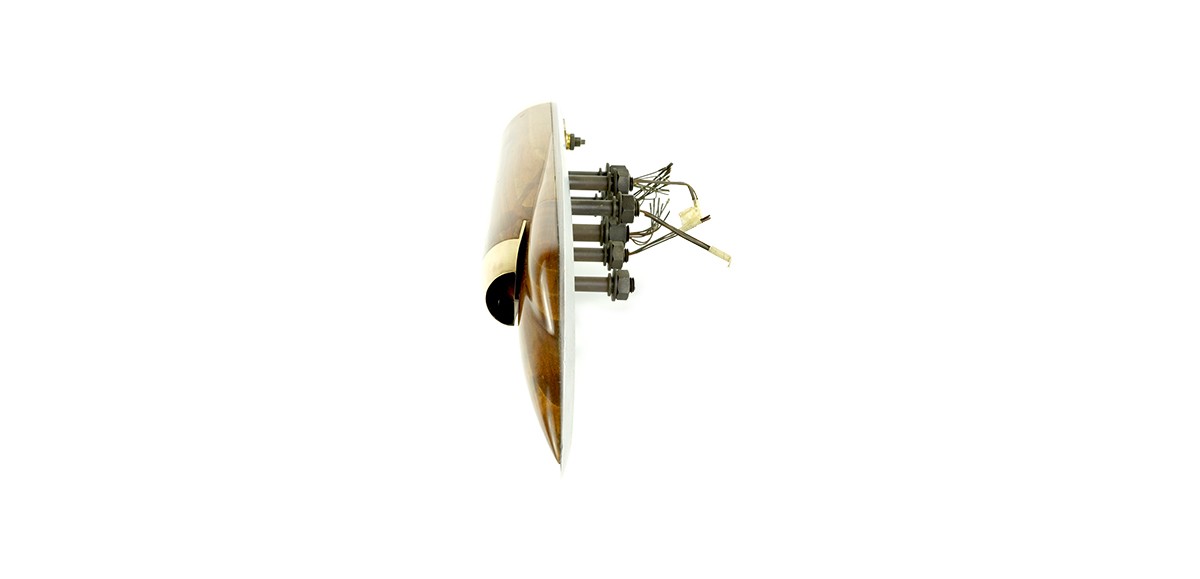
This is a very fine piece of our aviation history and one will appreciate its commanding features albeit its rather small size (length:70 cm, height: 20 cm, depth: 19 cm), and the fact that it can be displayed without any props: it fits at a perfect presentation angle, standing on its rear connections. This wind tunnel model is slightly different than those that can usually be found, but its subject and technical aspect are indeed appealing!

All comments